
Gyraf 1176 Compressor PCB Set
$29.95
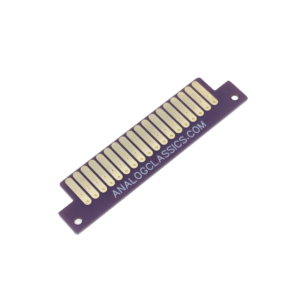
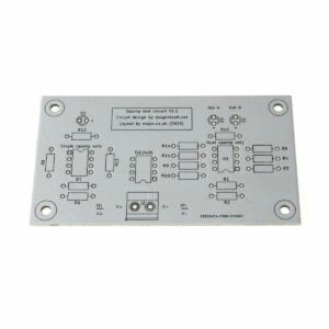
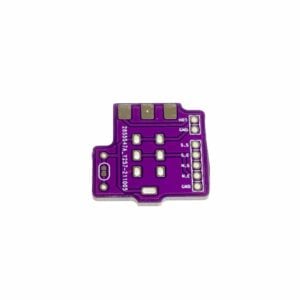
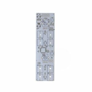
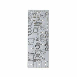
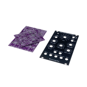
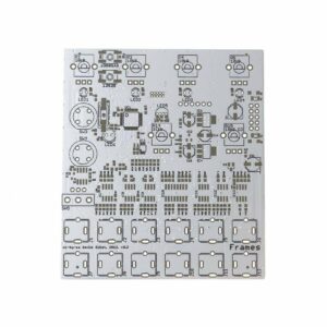
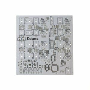
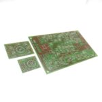
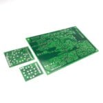
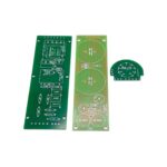
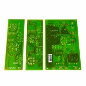
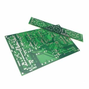
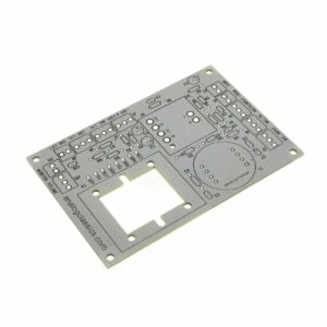
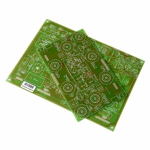
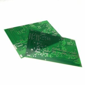
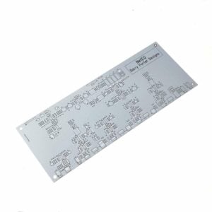
Only the blank PCBs pictured are included.
17 in stock
Gyraf Audio DIY 1176LN Compressor: A Comprehensive Guide
The Gyraf Audio DIY 1176LN Compressor offers audio enthusiasts a chance to build their own version of the classic UREI 1176LN rev#F. This project adapts the original design to accommodate readily available components, ensuring that anyone can recreate this legendary FET compressor. With detailed schematics, a comprehensive parts list, and step-by-step instructions, this guide will walk you through the entire process of constructing your very own 1176LN compressor.
Overview
The G1176 is a faithful adaptation of the original UREI 1176LN rev#F, utilizing standard European transistors, a Lundall output transformer, and rotary switches for easier enclosure layout. This project is perfect for DIY enthusiasts looking to dive into the world of audio compression with a hands-on approach.
Key Features
- Classic FET Compression: Emulates the sound of the original UREI 1176LN rev#F.
- Standard Components: Utilizes readily available European transistors and other components.
- Detailed Documentation: Includes a complete parts list, schematics, and adjustment procedures.
- Community Support: Access to forums and resources for troubleshooting and enhancements.
Building the Unit
Preparation:
- Component Verification: Ensure all components, especially resistors, are correctly valued before soldering.
- Heat Sink Usage: Apply a small heat sink to the 7824 voltage regulator to prevent overheating.
- PCB Inspection: Thoroughly check the PCB for shorts and solder blobs before powering up.
Assembly Tips:
- Pin Compatibility: Verify that NTE substitutes for semiconductors are pin-compatible.
- Transistor Placement: Be cautious with transistor placement as they are sensitive to incorrect mounting.
- Grounding: Properly connect the center tap of the 2x24V transformer to ground and ensure the chassis ground is connected at the input XLR(F) connector.
Adjustment Procedures
Q Bias:
- Bypass the unit, input a signal, and adjust the trimmer until a 1dB level drop is achieved.
Distortion Trim:
- Set the unit gain to unity and adjust the trimmer for minimum distortion.
GR Meter Zero:
- With no input signal, adjust the meter to read 0dBVU in GR mode.
GR Meter Tracking:
- Calibrate the gain reduction meter by adjusting the trimmer to reflect accurate dBVU readings during signal input and output comparisons.
Troubleshooting
Common issues include:
- Incorrect component values or placements.
- Overheating due to insufficient heat sinking.
- Short circuits on the PCB.
Resources:
- Online Forums: Access community forums for additional support and troubleshooting tips.
- Adjustment Guides: Refer to simplified adjustment procedures for easy calibration.
Enhancements and Customizations
SLAM Mode:
- Popularly requested, the SLAM or NUKE mode can be incorporated for more aggressive compression settings.
Input Transformer Option:
- An optional LL1540 input transformer can be added to enhance sound quality, although it’s not part of the original design.
Conclusion
Building the Gyraf Audio DIY 1176LN compressor is a rewarding project for audio enthusiasts, offering a hands-on approach to understanding and replicating one of the most iconic FET compressors in audio history. With detailed documentation, community support, and the flexibility to customize, this project ensures both a learning experience and a high-quality audio tool.
See the documentation tab for build docs.
Additional Resources
Explore these resources for more detailed instructions, troubleshooting tips, and community support as you embark on building your own 1176LN compressor.
*Analog Classics does NOT provide build support for this project.
| Brand | Analog Classics |
|---|---|
| Condition | New |
| Compatible Brand | Gyraf |
You may also like…


Related products