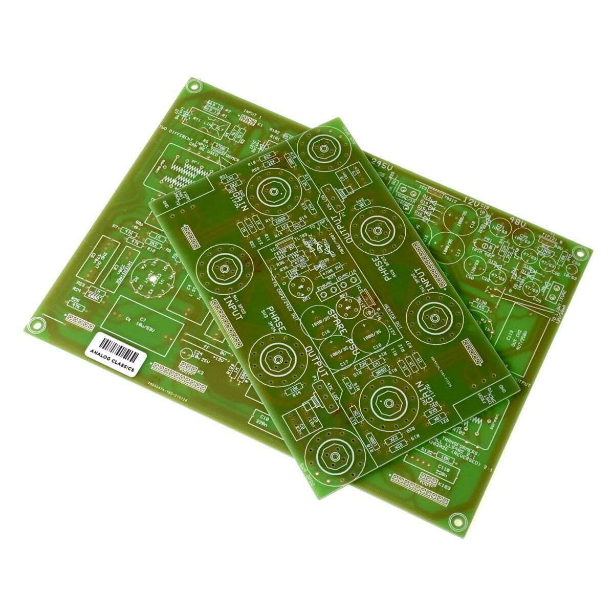
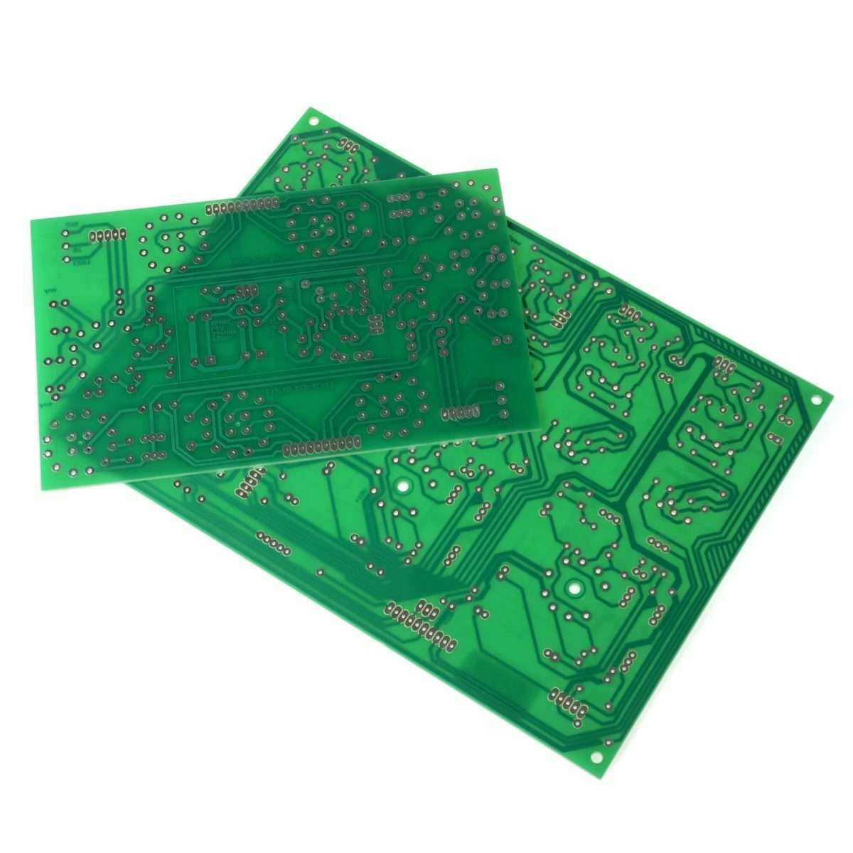
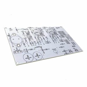
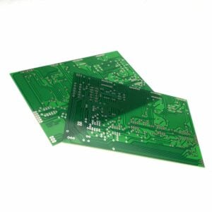
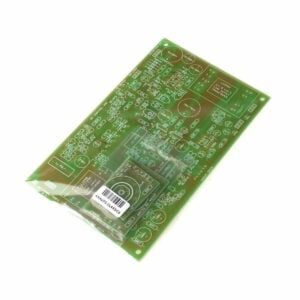
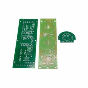
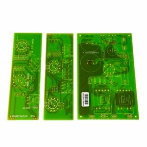
Our Gyraf G9 PCB set is the starting point for the Gyraf G9 Tube Mic Preamp DIY build. Please see the tabs below for additional information. Just the blank PCBs are included.
From Gyraf Audio… “The G9 contains two channels of real-tube, high-gain, transformer-balanced microphone preamplifiers with additional line and instrument inputs and transformer balanced output. It also features switchable phantom power, high-pass filter and phase reverse, as well as independent controls for input gain and output level – giving the user some creative options to work with.
The signal path contains only tubes, transformers and passive components, to preserve your signal integrety. VERY different from many “tubed” consumer products. But as we are not purists, we incorporate modern semiconductors in the powersupply sections – simply because this is way the easiest, cheapest and best solution available. For power amplifiers there’s quite an audible reason to use tubed power supplies, but for preamps I haven’t been able to spot any advantage so far.”
The G9 project is an adaptation of the Gyratec IX dual microphone/line/DI preamplifier to suit the DIY’ers demands. Searching the net, I’ve never come across a complete tube microphone preamp design, so I decided to share this version of our very popular design, the Gyratec IX. It is a classic, conservative design, that easily matches the performance of even the most expensive and esoteric units I’ve been able to compare it to.
I wish to thank Kev and Byron from Group DIY for test-piloting this project, and for their changes and comments on the original design. Without those guys this level of DIY-friendlyness would’nt have been even remotely possible.
Take a look at how Kev Ross builds this project Kev and Byron’s page on building the Gyraf G9.
The G9 contains two channels of real-tube, high-gain, transformer-balanced microphone preamplifiers with additional line and instrument inputs and transformer balanced output. It also features switchable phantom power, high-pass filter and phase reverse, as well as independent controls for input gain and output level – giving the user some creative options to work with.
The signal path contains only tubes, transformers and passive components, to preserve your signal integrety. VERY different from many “tubed” consumer products. But as we are not purists, we incorporate modern semiconductors in the powersupply sections – simply because this is way the easiest, cheapest and best solution available. For power amplifiers there’s quite an audible reason to use tubed power supplies, but for preamps I haven’t been able to spot any advantage so far.
I will try to update this page reguarly if anyone shows interest in its topics. Comments and corrections are extremely welcome, but I can’t promise to reply to all mail I receive. In “The Lab” – a forum on GroupDIY.org – there will surely be people that can and will answer most of your questions regarding the design, construction, and sourcing of parts. If you build this project and describe elements of the process, I’ll be more than happy to add it – or a link to it – here, so others can benefit from your experiences.”

Reviews
There are no reviews yet.